Jelenlegi hely
Recovering Diffeomorfic Shape Deformations without Correspondences
This page concerns a novel approach to estimate the parameters of transformations aligning two binary images. While other approaches obtain the solution via optimization our method traces back the problem to the solution of a system of nonlinear equations, which directly provides the parameters of the aligning transformation. It works without any time consuming optimization step or established correspondences. The advantage of our algorithm is that it is easy to implement, less sensitive to the strength of the deformation, and robust against segmentation errors.
Most of the classical registration methods first extract a set of corresponding landmarks and then use this information to find the aligning transformation between the images. However, the correspondence problem is challenged by strong deformations and radiomentric distortions. In many cases, however, the segmentations of the images are available, and binary image registration is a valid alternative.
 |
 |
We are interested in a direct solution without established correspondences so we integrate out individual point correspondences. It results in a system of two equations. In order to generate more linearly independent equations we making use of a set of nonlinear functions. Thus we obtain a system of nonlinear equations. Intuitively, each applied function generates a consistent coloring of the shapes and the equations match the volume of it over the shapes. The parameters of the aligning transformation are the unknowns of the system of equations and simply obtained as the solution of it.
 |
 |
 |
 |
 |
 |
| Example functions: The first row shows the coloring defined by the functions while the second row shows the corresponding volumes. | ||
1. Deformation fields
While gray-level images allow for a wide range of deformation fields, not every transformation model causes visible distortion on a binary image. For example, the effect of a localized deformation is not always observable. Therefore we focused only on some important class of deformations for which distortions are noticeable on binary shapes.
1.1. Planar homography
Perspective images of planar scenes are usual in perception of man made environments. In such cases, a planar scene and its image are related by a plane to plane homography, also known as a plane projective transformation. Estimating the parameters of the transformation between two views of the same planar object is a fundamental problem in computer vision with various applications (e.g. registration, shape matching, image mosaicing). It is well known that the mapping between two such images is also aplanar homography.
We tested our method on a synthetic database of 37 different shapes and their transformed versions, a total of ~1500 images of size 256×256.
 |
| Planar homography: Example results on synthetic images. The template and the registered observation were overlayed. The overlapping pixels are depicted in orange whereas nonoverlapping ones are shown in dark. |
1.2. Polinomial transformations
A broadly used class of deformations is the polynomial family. We tested the method on a synthetic database of 37 different shapes and their deformed versions, a total of ~1700 images of size 800 × 800.
 |
| Polynomail deformations: Example results on synthetic images. The template and the registered observation were overlayed. The overlapping pixels are depicted in orange whereas nonoverlapping ones are shown in dark. |
2. Robustness
The robustness of the proposed approach against two types of segmentation error as been also tested. In the first case we removed 5%,...,20% of the foreground pixels from the observation before registration, while in the second case we occluded continuous square shaped regions of size equal to 1%,...,10% of the whole shape.
| Removed pixels | Occluded region | |||
| Planar homography |  |
 |
 |
 |
| Polynomial transformations |  |
 |
 |
 |
| Example observations and registration results from the robustness tests.The overlapping pixels are depicted in orange whereas nonoverlapping ones are shown in dark. |
In the case of planar homographies our method provided good alignments up to as high as 20% missing pixels and 5% occlusions while in the polynomial case these limits were 5% and 2.5%.
3. Real images
The performance of our method has also been evaluated on real images in the context of two important application areas and in an industrial application.
3.1. Traffic signs
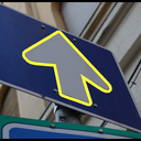
Traffic sign detection and recognition is an important application area where one of the key tasks is the matching of a projectively distorted sign with a template. Each template-observation image pair contains pictures of different traffic sign. The main challenges were strong deformations, segmentation errors and variations in the style of the depicted objects.
 |
 |
 |
 |
 |
|
 |
 |
 |
 |
 |
|
 |
 |
 |
 |
 |
|
 |
 |
 |
 |
 |
|
| Traffic signs. In the first and third row the templates, in the second and fourth row the observations with the overlayed contours of the registered images. | |||||
3.2. X-ray images
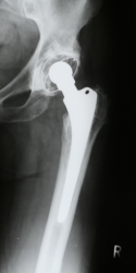
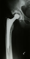
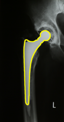
Hip replacement is a surgical procedure in which the hip joint is replaced by a prosthetic implant. An automatic analysis requires the registration of X-ray images. Since one is looking for deformations of the bone surrounding the implant, alignment must be based on the implant as it is the only imaged part which is guaranteed to remain unchanged from one image to the other. There are two main challenges here: One is the highly non-linear radiometric distortion which makes any graylevel-based method unstable. Fortunately, the segmentation of the prosthetic implant is quite straightforward. The second problem is that the true transformation is not a plane projective one, it also depends on the position of the implant in 3D space. Indeed, there is a rigid-body transformation in 3D space between the implants, which becomes a projective mapping between the X-ray images. Fortunately, the planar homography assumption is a good approximation here as the X-ray images are taken in a well defined standard position of the patient’s leg.
 |
 |
 |
 |
|||
| X-ray images. Templates and observations with the overlayed contours of the registered images. | ||||||
3.3. Industrial application: Visual inspection of printed signs
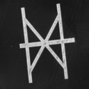
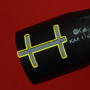
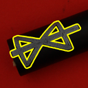
An important step in hose manufacturing for automotive industry is to print various signs on the hose surface in order to facilitate installation. The quality control of this process involves visual inspection of the printed signs. In an automated inspection system, this can be implemented by comparing images of the printed sign to its template, which requires the alignment of the template and observation shapes. The applied transformation model was described the physical model of the contact printing procedure:
- the stamp (basically a planar template of the sign) is positioned on the hose surface - 2D rotation and scaling;
- then it is pressed onto the surface - a cylindrical transformation.
- Finally the picture is taken - a projective transformation.
The main challenges are segmentation errors and complex distortions.
 |
 |
 |
 |
 |
|
 |
 |
 |
 |
 |
|
| Printed signs. In the first row the templates, in the second row the observations with the overlayed contours of the registered images. (Images provided by ContiTech Fluid Automotive Hungária Ltd.). | |||||
